Rangkaian Repeating Timermerupakan rangkaian yang akan kita bahas kali ini. This timer is based on a simple Monostable Circuit. The length of time the relay remains energized – the ON period – is controlled by the values of R3 & C2. And the length of time the relay remains de-energized – the OFF period – is controlled by the values of R4 & C3. With the component values shown – periods of up to 30 minutes are available.
The length of time the relay remains energized is controlled by the values of R3 & C2. And the length of the time the relay remains de-energized is controlled by the values of R4 & C3. Owing to manufacturing tolerances – the precise length of the time periods available depends on the characteristics of the actual components you’ve used.
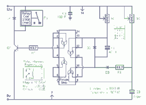
Berikut ini gambar skema rangkaian repeating timer :
You can choose component values that suit your own requirements. You should get about 70 seconds for every 1Meg/100uF. So 4M7 & 100uF will give about 6 minutes. And 4M7 & 1000uF will give about an hour. If your time periods don’t need to be too precise – and more-or-less is close enough – you can replace the pots with fixed resistors.
Do not use the “on-board” relay to switch mains voltage. The board’s layout does not offer sufficient isolation between the relay contacts and the low-voltage components. If you want to switch mains voltage – mount a suitably rated relay somewhere safe – Away From The Board.
The diode D1 makes this a one-shot timer. This means that after the programmed time delay of 3 hours, the relay will stay on until the circuit is reset. If the diode is omitted from the circuit then you get a repeating timer with the relay off for 3 hours, on for 3 hours, off for 3 hours, and so on until the circuit it reset.
Demikian penjelasan singkat tentang rangkaian repeating timer. Semoga artikel tentang rangkaian repeating timer ini bermanfaat bagi Anda. Selamat mencoba, semoga berhasil.


{ 0 komentar... Views All / Send Comment! }
Posting Komentar